Simpler - Safer - Cheaper
Make the most of Direct Current

The Set of Rules
As multiple aspects of the rules are patented, Partnership with the Current/OS foundation offers license rights to manufacture compatible products.
Current/OS is a new system approach of Electrical Distribution
- The electricity needs are increasing due to rapid growth of electrical vehicles (EV), digital and communications (IT), heating with heat pumps. At the same time, more affordable local electrical resources such as photovoltaic (PV) and battery storage systems (BESS), combined here and there with public grids limitations, leads more and more to microgrid applications in buildings, infrastructure and industry.
- The Direct Current (DC) electrical distribution seems more and more accurate to link DC sources (PV, BESS) with DC loads (EV, IT,…). DC also brings intrinsic benefits in long distance applications or in motor breaking energy harvesting.
- The power electronics components are more and more affordable, opening the door to solid state protection devices.
Current/OS is a system approach that make the most of Direct Current and power electronics
- Current/OS solves the usual objections raised against Direct Current electrical distribution and makes the best use of DC intrinsic features to offer a very high safety to people and assets.
- Current/OS defines energy management rules to make microgrids easy to control. It also enables a very opportunistic behavior of the microgrid to make the most of available electrical resources and power the loads according to their priority.
- Current/OS defines the communication model to open the door to software interaction with the electrical system. However, the intrinsic structure of Current/OS microgrids makes fully resilient to communication losses and cyber-attacks.
Safety is reaching unseen levels with Current/OS
- Current/OS defines EMC requirements for all connected devices.
- Current/OS specifies the current profiles at circuit connection, precharge and disconnection in order to allow black start and avoid nuisance tripping.
- Current/OS specifies the tripping criteria for detection of short circuit fault, earth leakage faults, serial arc fault, while ensuring bi-directional selectivity.
- Current/OS specifies the safety wire function that safely de-energize microgrid sections for maintenance purposes.
Energy Management is distributed at the circuit level to reach the highest resiliency and the most opportunistic behavior.
- Current/OS defines operating voltages and limits.
- Current/OS specifies the circuits voltage response and voltage dependent prioritization service with either on/off thresholds or linear adjustment of the power use/supply of the circuit.
- Current/OS specifies how to calibrate the devices, how to compensate line losses and voltage drops.
- Current/OS explains how to influence the loads and sources behavior beyond initial settings.
Zoning
The risk of an electrical installation always depends on the type of security, the voltage level and the maximum current in a segment.
A DC installation can be assigned to a certain risk. Based on the stored energy in batteries and the power that can be supplied by the installation at a certain point, a classification can be made to dangerous and less dangerous installation parts. For DC installations, five different risk classes are identified from zone 0 (highest risk) to zone 4 (lowest risk). These zones are described below.
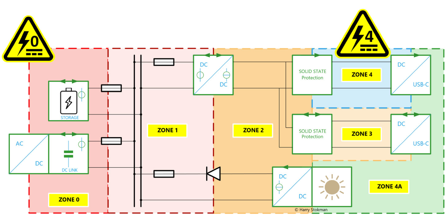
In this zone there are autonomous sources with a high power. This zone includes batteries (multiple linked batteries or batteries with large energy content), the public electricity grid and large PV installations. Voltages can be in the full range of low voltages up to 1500VDC.
- Very high overcurrent possible
- Multiple sources possible
In this zone there is voltage distribution (possibly busbars in equipment) powered from sources in zone 0 and protected on the downstream side of a classical electromechanical protection device like a fuse or a circuit-breaker. Voltages can be in the full range of low voltages up to 1500VDC. (Extra Low Voltage sources ELV, < 120 VDC or 60V may also be in wet conditions in this zone).
- High overcurrent possible
- Multiple sources possible
In this zone, current-bound LV sources in the full range of low voltages up to 1500VDC. (however < 120 VDC or 60V or 30 V may be in wet conditions).
- Overcurrent too small preventing electromechanical safety devices like fuses or circuit-breakers to perform its security function
- Multiple sources possible
- Bidirectional power flows
In this zone, there may be multiple sources and bidirectional "prosumers" (like battery systems). The protection is ensured by electronic devices with an ultrafast breaking time (a few micro seconds). Voltages can be in the full range of low voltages up to 1500VDC.
- Very limited overcurrent
- Absence of short-circuit power.
- Multiple sources possible
- Bidirectional power flows
In this zone there is only one source . The protection is ensured by electronic devices with an ultrafast (micro seconds) breaking time. Voltages can be in the full range of low voltages up to 1500VDC.
- No significant overcurrent
- Multiple sources not allowed
- Unidirectional power flow
Voltages
Multiple voltage bands are possible with Current/OS . Inside these bands, the voltage is a meaningful signal for all circuits to inform them about the power availability within the system and to make them react accordingly.
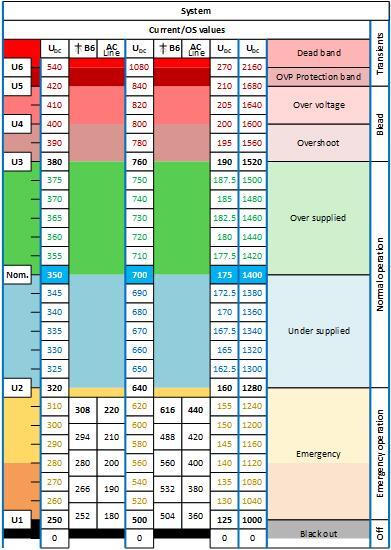
The figure below gives example of several voltage bands. Nominal voltage is just a label. But namely 350VDC and 700VDC are the most popular systems. Other systems with higher voltages (1400VDC) or lower (175VDC, 48VDC) are also possible
In the figure below, voltage bands are detailed.
With a traditional approach, voltage is defined by a nominal value and a tolerance. With Current/OS microgrids, nominal voltage value is just a label. The key values are the voltage band limits inside which the system operates. Inside these limits, the voltage is a meaningful signal for all circuits to inform them about the power availability within the system and to make them react accordingly.
For instance, the so-called 350VDC “nominal” system will in fact operate normally between 320VDC and 380VDC. 250VDC to 320VDC will be an emergency range. 380VDC to 540VDC will be an overvoltage area.
Current/OS devices are already available in 350VDC or 700VDC. They can also be delivered in 3 poles + and – 350VDC or + and – 700VDC. (1400VDC is feasible but not available for now).
As a core principle of Current/OS, the voltage level triggers the operating modes of loads and sources. Therefore, no communication system and central control is required to keep the application stable.
Droops control
Current/OS uses the voltage as a shared signal that reflects the power availability in the application to ensure the DC grid stability and energy management.
When voltage exceeds the middle or “nominal” value (350VDC or 700VDC), we are in an “oversupplied” situation. This voltage level will indicate loads to run as active as possible and to store as much energy as possible, be it electrical storage (batteries) or thermal storage (hot water, fridges and cold rooms, HVAC storage…). It can also trigger hydrogen generation.
When voltage is below the middle or “nominal” value (350VDC or 700VDC), we are in an “undersupplied” situation. This voltage level will indicate:
• for loads to de-activate according to priority settings,
• for thermal storage to be inactive,
• for electrical storage to feed the electrical loads
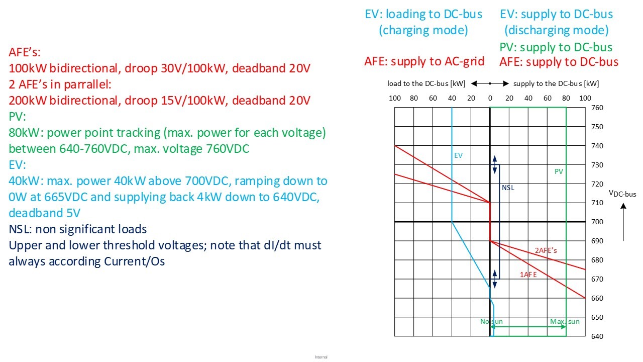
Circuits have different behaviors according to the voltage. These behaviors are defined as droop curves.
These droop curves describe the Power response (horizontal axis) to the Voltage (vertical axis).
All droop curves can be adjusted at commissioning level to define sources and load priorities. Droop curves can also be adjusted in real time to influence the behavior of the different circuits.